5W Qi Compatible Wireless Charger Transmitter.
This project features a wireless charger, adapted from a Microchip reference design. It uses a resonant coil with microcontroller-based control to deliver efficient wireless charging with built-in safety features.
Overview
The 5 W Qi-compatible wireless charger delivers efficient wireless power transfer using a resonant coil and microcontroller-based control, it also has built-in safety features. This project gave me hands-on experience in wireless power electronics and improved my PCB design skills.
Design
This wireless charger uses a resonant coil and a power stage controlled by a microcontroller to deliver efficient wireless power transfer while meeting the Qi standard. The design includes safety features, making it practical and robust.
Client
Andy Grove
This project presents a 5 W Qi wireless power transmitter, inspired by Microchip’s Qi 5W wireless transmitter reference design. I adapted this design to create a custom version suitable for demonstration and proof-of-concept. The transmitter is fully compatible with the Qi standard and is optimized for cost-efficient, safe, and reliable wireless power transfer up to 5 W. The design goals include maintaining high efficiency, ensuring robust foreign-object detection (FOD), and providing full software control of the power and communication loop.


Core System Architecture
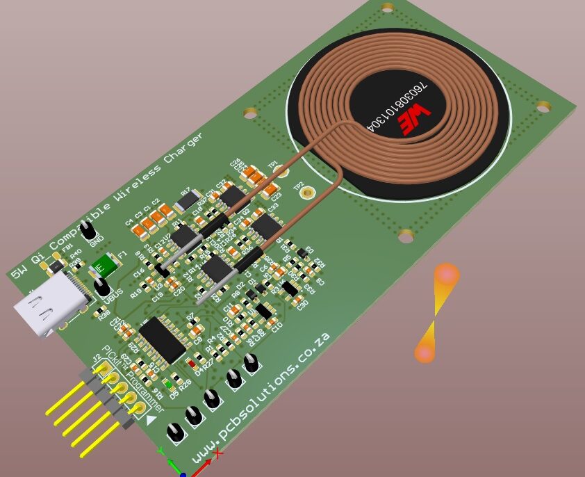
Input & Power Stage: Accepts a 5 V input (e.g. from USB-C or standard 5 V adapter), converting it via a power stage (H-bridge or half-bridge) to drive the resonant coil. The design supports a working frequency range (approx. 110 kHz to 205 kHz) with distributed capacitance (DCY) compensation to maintain resonance and efficiency. Microchip
Resonant Coil & Matching Network: A transmitting coil tuned with series/parallel capacitors to form a resonant tank. It couples magnetically to the receiver coil in the end device. Proper tuning, layout, and shielding are critical to reduce losses and maintain stability.
Control & Communication: The Qi state machine, FOD detection, and control loops are handled in firmware. In the reference, a PIC16F (or equivalent) microcontroller runs the state machine and monitors feedback to regulate power. Microchip
Protection & Regulation: Safety features such as over-current, over-temperature, and thermal shut-off are included. FOD (foreign object detection) is implemented such that the threshold scales with transmitter power. Microchip
Efficiency & Performance: The reference target is over 70% transfer efficiency in many real-world conditions.

What I did and Learned
I used the Microchip reference design as a foundation for learning and adaptation, not as a black box: I studied the reference schematic and documentation closely, then reimplemented and modified as needed for my own version.
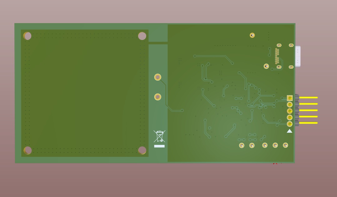
I created custom schematics and PCB layouts, optimizing component placement, trace routing (especially in the resonant and high-current paths), and layout constraints for EMI suppression.
I annotated and explained critical functional blocks in my documentation (e.g. resonant tank, FOD detection circuit, microcontroller interface), highlighting where design trade-offs occur (efficiency vs safety, layout vs stray capacitance).
I measured and validated performance (e.g. power transferred at different coil separations, thermal behavior, FOD response) to compare with theoretical expectations.
I documented deviations or enhancements I made (e.g. alternative component choices, layout tweaks, optional features) and discussed how the design might scale or be improved further (e.g. higher power levels, multi-coil, alignment aids).